It seemed like nearly half of all my interior lights were burned out — the instrument cluster, steering wheel, HVAC controls, door panels… everything had about 50% of the bulbs actually working. Having always been a Ford owner, is this some kind of Chevy thing? The gear selector display (also referred to as the PRND321 display) was also not working, which turned the task of shifting gears into more guess work than it should have been. Time to change all that!
First and foremost, lets start with the before and after photos:


While I have literally hundreds of LED’s in my office of 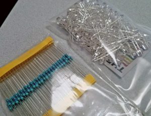 every color there is, I did not have many that were flat-top, which tend to have a larger viewing angle (better light dispersal to reduce “hot” spots) than the domed LED’s I had amassed. A late Thursday night order for blue LED’s and 470 ohm resistors made their way to me by Saturday afternoon. By that time I had already removed my instrument panel and had it all ready for the LED replacements.
 With the instrument panel removed, I turned all the needles as far counter-clockwise as they’d go. Then I marked their locations. This will help re-position them again during assembly. The needles all popped-up using a fork shoved under neither of them very carefully and prying until they came up. It took more force that I would have thought, but it worked and nothing broke. I set them to the side and lifted the top cover off to reveal the circuit board below.
 The circuit board may appear a bit daunting, but it’s really not too bad. All the dash lights I’d be replacing are located in the white masked area. There are 8 of them in total on my board (some have a 9th bulb in the bottom left area, mine is blank). I removed all the old bumps and blue plastic stands simply be breaking them off, no soldering needed for that. Left behind are smooth solder pads. On each solder pad I placed a nice blob of solder. This makes installing the LED’s and resistors easy, since all I’d have to do is heat up the new solder blob and insert the wire lead, with no additional solder needed. In this particular photo, the middle-right LED failed to work after replacement, so I simply removed it and stuck in a new LED/resistor combo.


The PRND321 display was the next item I tackled. The 7 resistors circled in blue (511 resistors) are the typical problem when the display goes out. From the factory very little solder was used to hold them down. They’re also said to be underratted for their job, so heat becomes an issue. The heating and cooling between using can cause the solder joints to break, which is exactly what happened here. While I couldn’t visually see any issues, slight prying from the sides of them with a small flat-head screwdriver showed that several were broke and bent right up with very little force. The remedy was to simply apply additional solder to each joint. A quick test proved the fix to be successful!
While I had this all in my office, I was able to power the backlights (just the lights in the white area of the board) using a 12V adjustable power supply. There’s just two wires you need to connect:
 The negative wire (wire on left) goes to ground, and the wire to the right of it goes to your positive DC power supply. I found the LED’s would operate between an input voltage of 3-12V. This is the same pin that the vehicle’s dimmer switch is connected to, so all we’re doing here is simulating the trucks dimming feature.
There is a lot of information out there with some very good, detailed photos of doing such an LED swap, therefore I did not go too deep into my own personal swap. But I did want to provide a general overview, if nothing more than for my own records, which much of my site is for anyways.